Complete Brake Repair Job; What's the Process?
A brake assembly diagram provides a visual representation of the various parts and their connections, allowing for a better understanding of how the brakes actually work.. rotor, brake pads, and brake lines. These parts work together to slow down or stop the vehicle when the driver applies pressure to the brake pedal. The diagram illustrates.

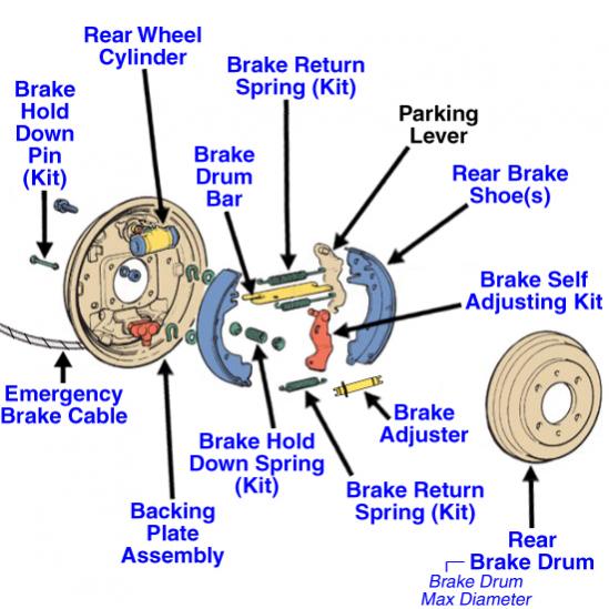
Repair Guides Rear Drum Brakes Brake Shoes
ABS Control Module Found on vehicles with ABS brakes, the module performs diagnostic checks of the ABS braking system and determines when to send the correct pressure to each wheel to prevent the wheels from locking up. Brake Booster Reduces the amount of pressure needed for braking to allow any driver to operate the brakes.
Brake System Repair Process Explained by Pop's Auto, Orlando, Fl
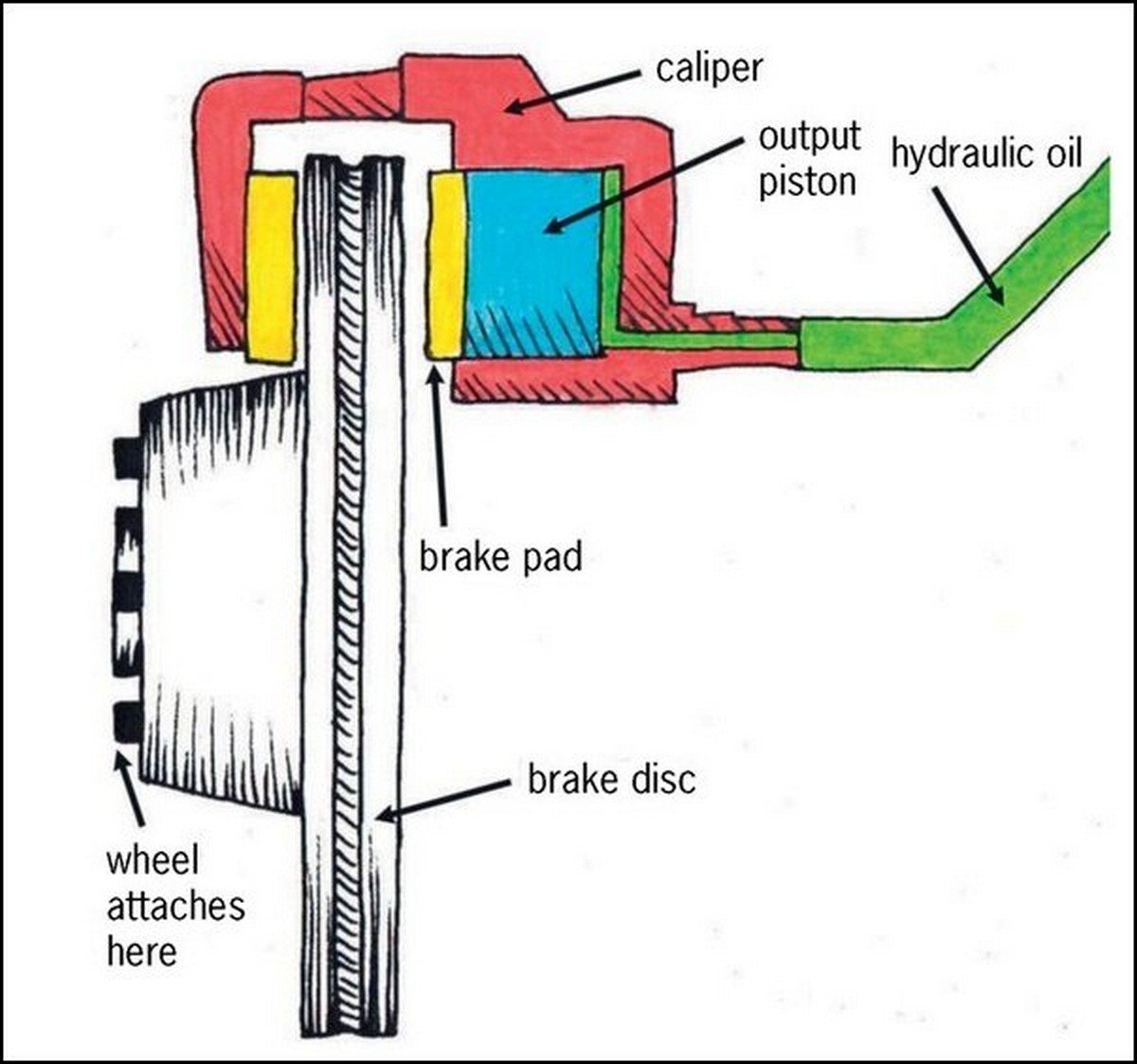
Disc Brake Diagram How disc brakes work: Check out the diagram; it shows the disc brake layout with a floating caliper, which is the most common design in modern cars. The brake disc or 'rotor' (the green part) is installed on the hub. The wheel (not shown here) is installed on the same hub. The brake disc rotates together with the wheel.

Automotive Braking System infographic diagram showing front disk and
A brake caliper diagram is a visual representation of all the different parts and components that make up a brake caliper. The brake caliper is a crucial component of a disc brake system, which is widely used in modern vehicles for its superior stopping power and control.

2010 Ford F150 Rear Brakes Diagram
1) Master Cylinder 2) Brake Rotor (Disc Brakes) 3) Brake Drum (Drum Brakes) 4) Brake Pad (Disc Brakes) 5) Brake Caliper (Disc Brakes) 6) Brake Shoe (Drum Brakes) 7) Brake Booster 8) Brake Pedal 9) Wheel Speed Sensors (ABS) 10) ABS Module 11) Brake Lines Importance of Brake Fluid Materials Used in Brake Systems Car Brake System Components
Diagram Of Car Braking System
BRAKE ADJUSTERS DISC BRAKES CALLIPER IDENTIFICATION MAXX22T HDT-415 Calliper Wabco HDT-377 & -430 Calliper Knorr-Bremse SN7 Calliper Knorr-Bremse SB7 Calliper CONMET BRAKE ROTOR IDENTIFICATION Early Type Parallel Brake Rotor Late Type Offset Brake Rotor

Repair Guides Drum Brakes Drum Brakes
The brake disc (or rotor) is the rotating part of a wheel's disc brake assembly, against which the brake pads are applied. The material is typically gray iron, a form of cast iron. The design of the discs varies somewhat. Some are simply solid, but others are hollowed out with fins or vanes joining together the disc's two contact surfaces.

Diagram Of Brake System On Car
Drum Brake Diagram Now let's put it all together. The drum brake diagram below shows how all the parts of the brake work together. For more brake topics and links to related auto articles, check out the links below. Related HowStuffWorks Articles How Brakes Work 1. 5 6 Print | Citation Advertisement Advertisement Advertisement
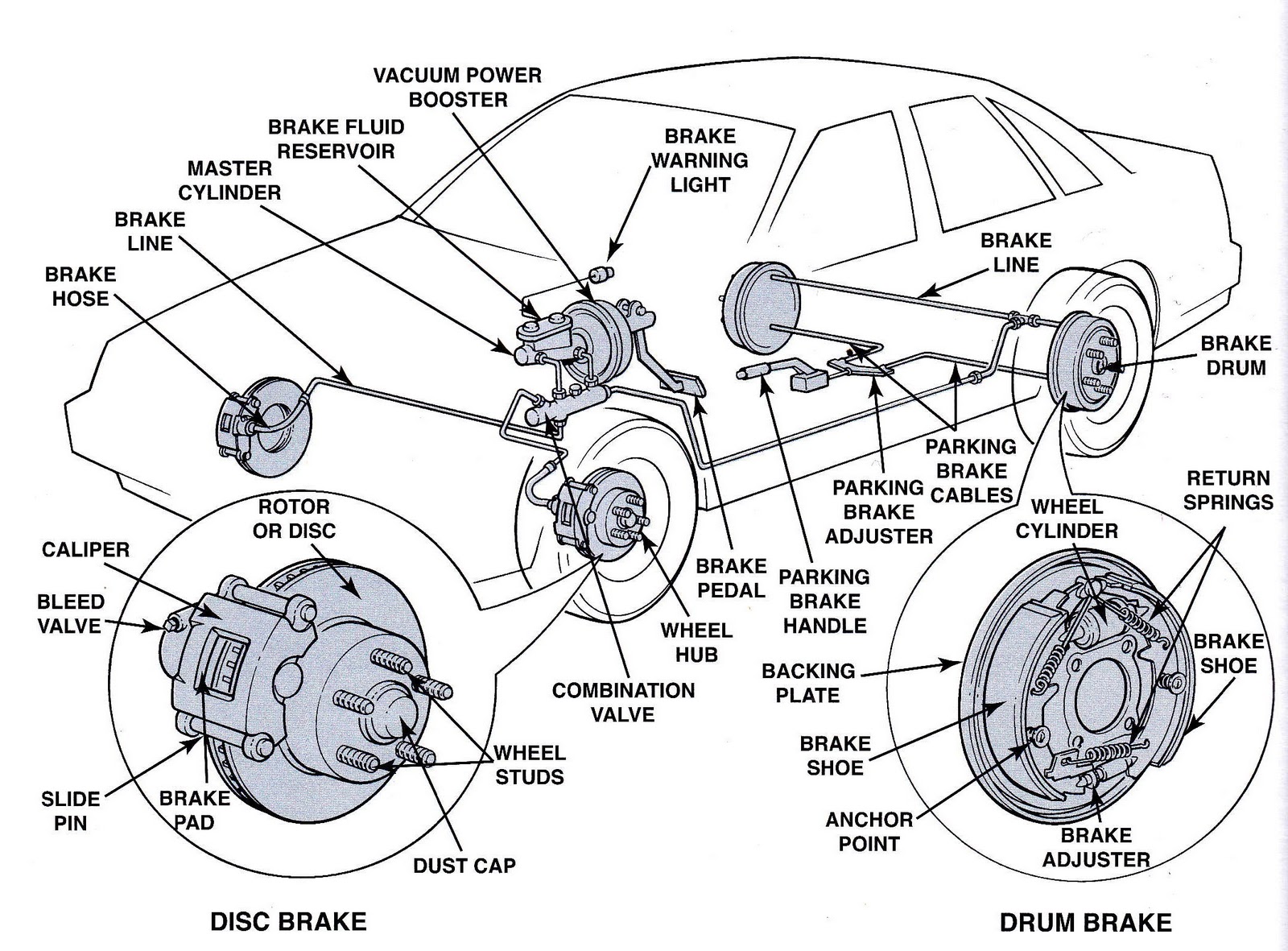
Diagram Of Car Brakes
(Image/Wayne Scraba) Here's a look at the collection of little parts you'll need in order to assemble (and completely rebuild) one rear drum brake. You'll have to reuse some of your original park brake hardware. (Image/Wayne Scraba) Begin the assembly process with the wheel cylinder (s). They're installed as shown here. They can only go in one way.

Repair Guides Rear Drum Brakes Introduction
This diagram illustrates the 2 most common types of fittings used in street rod brake systems. The first is the inverted flare type, which is used by most domestic production cars and trucks, and on the bottom is the -3 AN (which is pronounced as dash three A N or number three A N).

Schematic illustration of an automobile disc brake [1] Download
1. Brake Pads The brake pads are the outermost part of the braking system and true workhorses. The brake pads are one of the brakes components that contact and apply pressure and friction to the brake rotors — the discs that actually slow and stop the vehicle.

Repair Guides Rear Drum Brakes Brake Shoes
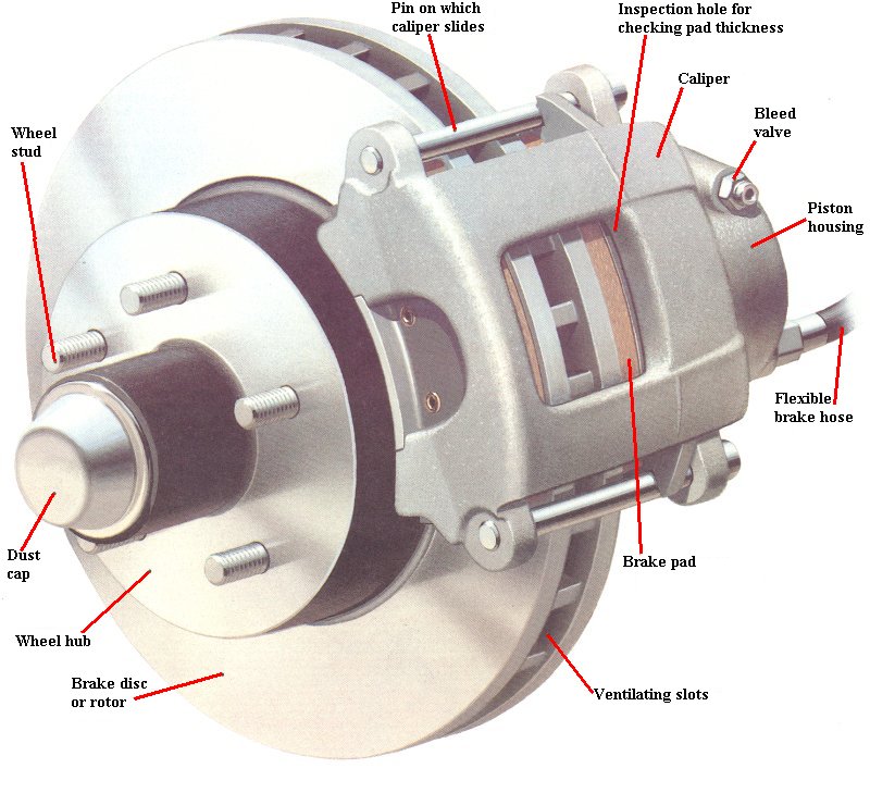
This diagram shows the basic parts that make up a disc brake system. Related HowStuffWorks Articles How Brakes Work How Master Cylinders and Combination Valves Work How Drum Brakes Work How Power Brakes Work How Anti-Lock Brakes Work 1. 5 6 Print | Citation Advertisement Advertisement Advertisement

Car Brake Anatomy Anatomical Charts & Posters
When the driver steps on the brake pedal, the power is amplified by the brake booster (servo system) and changed into a hydraulic pressure (oil-pressure) by the master cylinder. The pressure reaches the brakes on the wheels via tubing filled with brake oil (brake fluid). The delivered pressure pushes the pistons on the brakes of the four wheels.
Drum brake and Disc Brake Pros and cons
Diagram of Drum Brakes Drum brakes are a brake system with brake drums (rotor) that rotate with the wheels. Inside each drum are brake shoes fitted with brake linings (friction material). Pistons (pressure mechanism) press against the drums from the inside to generate braking force, thus making it possible to decelerate and stop the vehicle.

Repair Guides Front Disc Brakes Front Brake Caliper
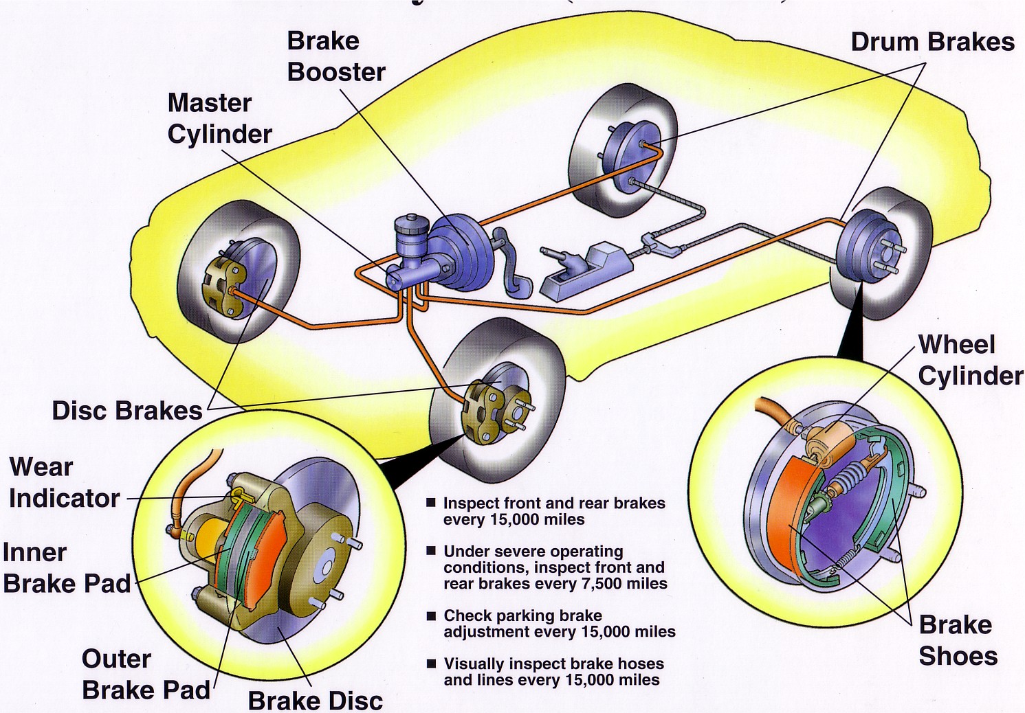
This diagram provides both a closeup view and an example of where the brakes are located in your vehicle. For more articles on brakes and related automotive topics, check out the links below. How Brakes Work How Master Cylinders and Combination Valves Work How Drum Brakes Work How Disc Brakes Work How Anti-lock Brakes Work
Car Brake Assembly Diagram
The four major parts of a disc brake system are the caliper, rotor, brake pads, and hardware. These four parts synergize in the braking system operation. The caliper is responsible for slowing the car down through the friction created with the rotors when it pushes the brake pads against the component.